|
GLsun Science & Tech Co., Ltd
|
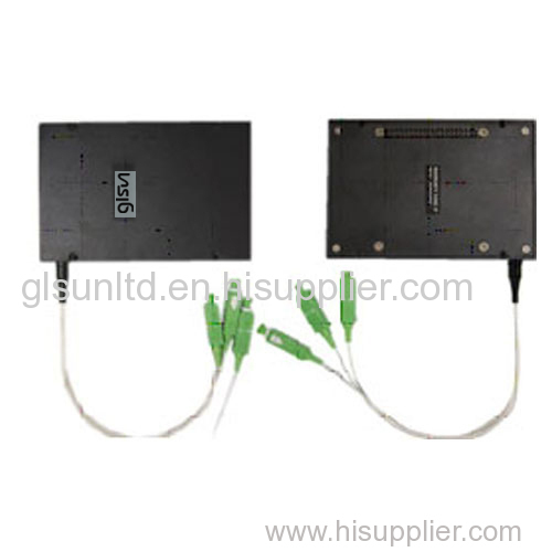
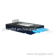
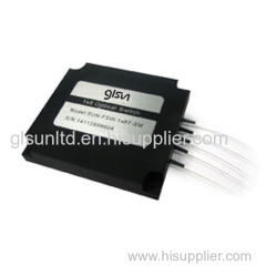
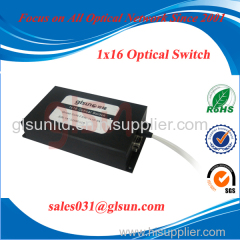
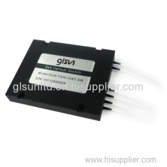
OLP Module Optical Line Protection Module (Multi Channel Optical Switch)
| Price: | 500.0 USD |
| Payment Terms: | T/T,L/C |
| Place of Origin: | Guangxi, China (Mainland) |
|
|
|
| Add to My Favorites | |
| HiSupplier Escrow |
Product Detail
1.Wide Wavelength Range
2.Low Crosstalk
3.High Stability, High Reliability
4.Modularized Design
5.Competitive Price, Fast Delivery
OLP Module Optical Line Protection Module (Multi Channel Optical Switch) - Features
•Wide Wavelength Range
•Low Crosstalk
•High Stability, High Reliability
•Modularized Design
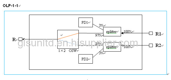
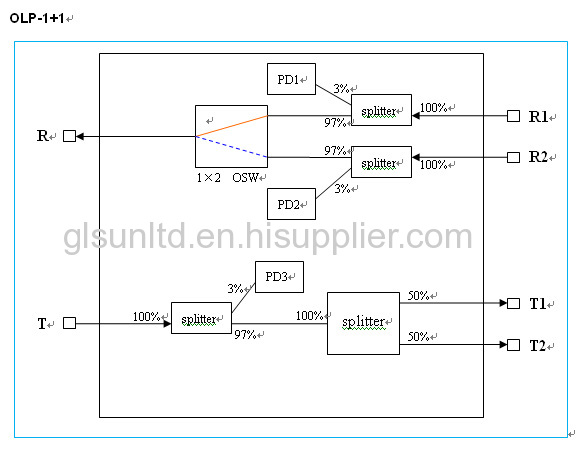
OLP Module Optical Line Protection Module (Multi Channel Optical Switch) - Working Theory

OLP Module Optical Line Protection Module (Multi Channel Optical Switch) - Specifications
Parameters | Unit | OLP-1:1 | OLP-1+1 | OLP-1-1 |
Wavelength Range | nm | 1260 ~ 1650 | ||
Test Wavelength | nm | 1310 / 1550 | ||
Insertion Loss | dB | TX<1.2,RX<1.2 | TX<4,RX<1.2 | <1.2 |
Return Loss | dB | SM ≥ 45 | ||
Crosstalk | dB | SM ≥ 50 | ||
PDL | dB | ≤ 0.20 | ||
WDL | dB | ≤ 0.30 | ||
PD dark current | nA | <1 | ||
PD responsivity | mA/W | 24 ~ 40 | ||
PD report accuracy | dB | ±0.5 (at -50 to 23 dBm) | ||
Operating voltage | V | 4.5 ~ 5.5 | ||
Operating current | mA | 80 ~ 120 | ||
Operating Temperature | ℃ | -5 ~ +60 | ||
Storage Temperature | ℃ | -30 ~ +80 | ||
Dimension | mm | 120×80×18 | ||
OLP Module Optical Line Protection Module (Multi Channel Optical Switch) - Pin Configurations
OLP-1-1
Pin No. | Signal Name | I / O | Description | |
1 | 2 | NA | Not applicable | |
3 | PD2- | Output | PD2 Cathode output | |
4 | PD2+ | Output | PD2 Analog output | |
5 | PD1- | Output | PD1 Cathode output | |
6 | PD1+ | Output | PD1 Analog output | |
7 | 8 | NA | Not applicable | |
9 | 10 | NA | Not applicable | |
11 | 12 | NA | Not applicable | |
13 | 14 | NA | Not applicable | |
15 | 16 | NA | Not applicable | |
17 | 18 | NA | Not applicable | |
19 | 20 | STA | Output | Switch status |
21 | 22 | S1 | Input | Switch electrical drive |
23 | 24 | S2 | Input | Switch electrical drive |
25 | 26 | NA | Not applicable | |
27 | 28 | D_+5VDC | Power | Digital power supply |
29 | 30 | D_GND | Power | Digital ground |
31 | 32 | A_GND | Power | Analog ground |
33 | 34 | NA | Not applicable | |
35 | NA | Not applicable | ||
36 | NA | Not applicable | ||
37 | NA | Not applicable | ||
38 | NA | Not applicable | ||
39 | 40 | NA | Not applicable | |
customization is available
OLP-1+1
Pin No. | Signal Name | I / O | Description | |
1 | 2 | NA | Not applicable | |
3 | PD2- | Output | PD2 Cathode output | |
4 | PD2+ | Output | PD2 Analog output | |
5 | PD1- | Output | PD1 Cathode output | |
6 | PD1+ | Output | PD1 Analog output | |
7 | 8 | NA | Not applicable | |
9 | 10 | NA | Not applicable | |
11 | 12 | NA | Not applicable | |
13 | 14 | NA | Not applicable | |
15 | 16 | NA | Not applicable | |
17 | 18 | NA | Not applicable | |
19 | 20 | STA | Output | Switch status |
21 | 22 | S1 | Input | Switch electrical drive |
23 | 24 | S2 | Input | Switch electrical drive |
25 | 26 | NA | Not applicable | |
27 | 28 | D_+5VDC | Power | Digital power supply |
29 | 30 | D_GND | Power | Digital ground |
31 | 32 | A_GND | Power | Analog ground |
33 | 34 | NA | Not applicable | |
35 | PD3- | Output | PD3 Cathode output | |
36 | PD3+ | Output | PD3 Analog output | |
37 | NA | Not applicable | ||
38 | NA | Not applicable | ||
39 | 40 | NA | Not applicable | |
customization is available
OLP-1:1
Pin No. | Signal Name | I / O | Description | |
1 | 2 | NA | Not applicable | |
3 | PD2- | Output | PD2 Cathode output | |
4 | PD2+ | Output | PD2 Analog output | |
5 | PD1- | Output | PD1 Cathode output | |
6 | PD1+ | Output | PD1 Analog output | |
7 | 8 | NA | Not applicable | |
9 | 10 | NA | Not applicable | |
11 | 12 | NA | Not applicable | |
13 | 14 | NA | Not applicable | |
15 | 16 | NA | Not applicable | |
17 | 18 | NA | Not applicable | |
19 | 20 | STA | Output | Switch status |
21 | 22 | S1 | Input | Switch electrical drive |
23 | 24 | S2 | Input | Switch electrical drive |
25 | 26 | NA | Not applicable | |
27 | 28 | D_+5VDC | Power | Digital power supply |
29 | 30 | D_GND | Power | Digital ground |
31 | 32 | A_GND | Power | Analog ground |
33 | 34 | NA | Not applicable | |
35 | PD3- | Output | PD3 Cathode output | |
36 | PD3+ | Output | PD3 Analog output | |
37 | PD4- | Output | PD4 Cathode output | |
38 | PD4+ | Output | PD4 Analog output | |
39 | 40 | NA | Not applicable | |
customization is available
OLP Module Optical Line Protection Module (Multi Channel Optical Switch) - Dimension

OLP Module Optical Line Protection Module (Multi Channel Optical Switch) - Ordering Information:
SUN-OPS-M-A-B-C-D-E-F-G
A | B | C | D | E | F | G |
Type | Fiber Type | Test Wavelength | Tube Type | Fiber Length | Connector | Dimension |
Optical Line Protection System Module X: Others | SM: SM, 9/125 | 1310: 1310nm | 90:900um | 05: 0.5m±5cm | OO:None | 01: 120×80×18(ABS) |

Related Search
Find more related products in following catalogs on Hisupplier.com
Company Info
GLsun Science & Tech Co., Ltd [China (Mainland)]
Business Type:Manufacturer
City: Guilin
Province/State: Guangxi
Country/Region: China (Mainland)